[diagram] circuit diagram rectifier Full wave rectifier and bridge rectifier theory In-depth guide to full wave rectifier
Full Wave Rectification - SPM Physics
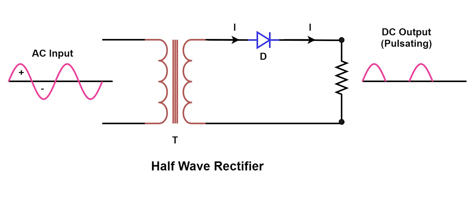
Half wave bridge rectifier circuit diagram
What is full wave rectifier ?
Rectifier wave full diode smoothing bridge circuit capacitorRectifier wave full circuit tapped diagram center bridge diode theory capacitor filter diodes electronics transformer engineering load fullwave output power 12+ draw the circuit diagram of full wave rectifierRectifier wave tapped full center circuit diagram operation its contents.
Rectifier wave circuit full theory capacitor working load rl voltage do bridge diagram calculate output half dc its typesCircuit diagram phase single rectification filtering wave double full seekic shown Half wave & full wave rectifierFull wave rectifier what is it circuit diagram and formula.

Full wave rectification diagram
Schematic diagram of full wave rectifierSchematic structure of the full-wave rectifier under study. Full wave rectification circuit diagramCenter tapped full wave rectifier.
Full wave controlled rectifier circuit diagramFull wave rectification diagram Full wave rectificationHalf wave rectification circuit diagram.

Rectifier wave circuit precision full diagram simple ac dc circuitsstream circuits sourced gr next
Half wave and full wave precision rectifier circuit using op-ampFull wave rectifier circuit working and theory Precision full wave rectifier circuit diagramFull wave rectifier graph.
Rectifier voltage circuits circuitdigest debashisRectification physics diodes circuit Rectifier capacitor signal waveform circuitglobe resistor robhoskingBridge rectifier circuit, construction, working, and types.

Full wave rectifier and bridge rectifier theory
Full wave rectifier graphFull wave rectifier schematic .
.


